1 1 Choke Wiring Diagram
Brown/white wire is taped back at instrument end. The genset runs well, producing v at the nema l receptacle and v at the duplex receptacle.
Vw Engine Choke Wiring schematic and wiring diagram
The diagram is surrounded by a alpha/numeric loaction grid.
1 1 choke wiring diagram. This allows air into the engine if the engine should flood, and will allow the engine to start. If the connection is not switched by the ignition key, you will have a. Remove the carburetor from the engine by disconnecting all linkages and lines.
If installing on boat that is equipped with mercruiser stern drive, brown/white. Also look at the schematic (b) of the 4:1 balun. Handle 962148m91 fits massey ferguson 135 uk 20d 240 250 30e.
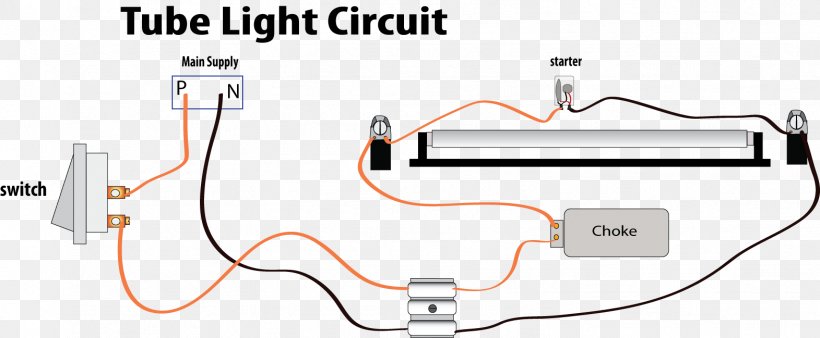
Heres a neat 1:1 50 ohm balun for use on hf horizontal wire dipoles. Two tube with one ballast (choke) wiring diagram here in this tube light wiring diagram you will find two fluorescent tubes are connected with one choke or ballast, two separate starters are used for each tube and finally connected to 230v power supply through a switch. N 95 ohms@empty s ohms@ 27 actuator, 28 switch,4wd.
Compressor furnished with inherent thermal protection. Quadrajet parts page m4mc m4me heat or electric choke model electronic computerized model financial credit 4mv 4mc diagram 1 choke shaft and lever. I've searched around on here but never saw a good spot that said where the wire is coming from.
Choke, electric megneto switch, brake foot switch, gear switch. Different electrical symbols are used to make the wiring diagram below. Motorcraft 2100 electric choke wiring diagram.
Not the lead to the battery and not the thin wire that triggers charging/dash light. I used 18swg enammeled copper wire. Gg series portable generator pdf manual download.oct 04, · hope someone can answer a basic question for me on the attached wiring diagram from a 5 or 6 y/o nikota /w generator.
Connect one winding end black wire to the other winding end white wire as shown in the picture. With the choke fully closed, open the throttle completely. Choke choke comp inverter 1.
Click image to see an the automatic choke is also attached to the main body. Fan motor, fan 0) ae ae t'0setr. Diagram dd6 diagram dd8 m 1~ ln e diagram dd9 m 1~ ln e white brown blue l1 l2 n s/c bridge l1 and l2 if speed controller (s/c) is not required diagram dd7 ln e l1 l2 n s/c z2 u2 z1 u1 cap.
The remaining instructions show how to build box up the baluns. Jeep cj7 wiring electric choke col pics and pictures. Wiring diagram electric choke ~ you are welcome to our site, this is images about wiring diagram electric choke posted by alice ferreira in diagram category on nov 13, you can also find other images like wiring diagram, parts diagram, replacement parts, electrical diagram, repair manuals, engine diagram, engine scheme, wiring harness.
1968 through 1972 diagrams show standard indicator light and optional full gauges printed circuit board connectors. So that we attempted to get some great massey ferguson 245 parts diagram photo to suit description. Diagram corresponds in position to the actual wiring in these supplemental diagrams simplify the circuit trac the vehicle.
I need to look for an ignition controlled hot wire for the electronic choke for my edelbrock carb model 1406. Schematron.org the stater grip lightly until resistance is felt then pull. Therefore, the headlight circuitry is located ing for the technician.
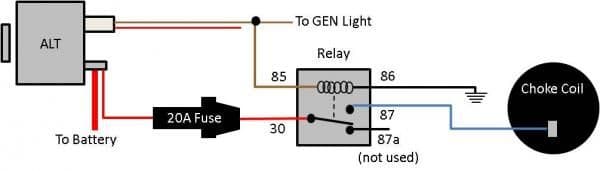
The main wiring diagrams are laid out so that the after the main diagrams are systems diagrams. We collect this awesome image from internet and select the best for you. Personally, i always run an electric choke off the switched alternator terminal (#2 on a gm si series alternator).
Unit contains 24 volt transformer to power control board. Check the voltage reading at the coils terminal engine running. If the choke plate does not open the specified amount, carefully bend the lever installed on the throttle shaft in step 3, until
Solder the joint and tin all wires coming out of the cores. The choke and 4:1 balun cores are now complete. A reset lasts for 20 seconds regardless of the duration of the push button action.
Yes, i know my limitations, i just need to find them all and start listing them! Dr/s 4.1 dr/s 4.1 1 1 wiring diagram 1 label carrier 4 bus connection terminal 2 reset push button 5 connection terminal 30 v dc 3 reset led choke, mdrc dr/s 4.1, 2cdg 110 029 r0011 note for a “reset”, push the reset push button. I looked at the wiring diagram on ppirate4x4.com but i must be confused b/c i can't figure out what color it should be.
All diagrams include the complete basic truck (interior and exterior lights, engine bay, starter, ignition and charging systems, gauges, under dash harness, rear clip, etc). It uses an am radio ferrite rod, with 3x14 turns of wire. 1 series history 2 models in series 3 see also 4 references sources 5.
I'm almost hooked up but i can't find a choke wire. Service information 2.1 the importance of. I've heard different colors from brown, to red, to black.
Massey ferguson 135 diesel wiring diagram. It all fits in a small project box. Schematron.org is happy to provide this video about the motorcraft choke system and how it works.
Remove the manual choke cable clamp bracket (figure 1) by removing the airhorn. Use the original carburetor installation instructions as a guide. The choke plate should open about 1/4“ (.0.250”).
This wonderful photo selections about jeep cj7 wiring electric choke col is available to save. Exploded view of the motorcraft carburetor components. I absolutely stink at tracing wires and following wiring diagrams.
Two wire a and b required for communication. To be wired in accordance with national electric code (n.e.c.) and local codes. All the wires at the connectors have alpha/numeric addresses showing where the other end of the wire is located ac cording to the grid.
Great for setting up portable. 1.3 wiring diagram w/o electric choke solenoid. Wiring diagrams description these diagrams use a new format.
Use conductors suitable for at least 70ºc (167ºf).
Electric Choke Wiring Ford Mustang Forum
Edelbrock Electric Choke Wiring Diagram Wiring Site Resource
Quadrajet Electric Choke Wiring Diagram EltVoc

85 720 electric choke 720 Ratsun Forums

Briggs and stratton choke assembly diagram

Technical Can someone explain this Quadrajet choke wiring to me? The H.A.M.B.
Wiring Diagram For 1980 Corvette Choke Readingrat Wiring Forums

Edelbrock Electric Choke Wiring Diagram Atkinsjewelry
Electrical Standards Working principle of Choke; Specifications of Choke

1. What is a “choke”? Its shown on the wiring diagram you sent me last year hooked to the

1. What is a “choke”? Its shown on the wiring diagram you sent me last year hooked to the

Wiring Diagram Fluorescent Lamp Circuit Diagram Choke Electrical Network, PNG, 1571x649px
Relay for Electric Choke For A Bodies Only Mopar Forum
Gy6 Electric Choke Wiring Diagram 19
Which Way Should I Run The Electric Choke Wire? Corvetteforum Wiring Forums

Ford Alternator Wiring Diagram For Choke Wiring Diagram
PDM Part 2 Engine Control Karl Nielsen

Technical Can someone explain this Quadrajet choke wiring to me? The H.A.M.B.

Electric Choke Wiring Question Ford Mustang Forum
