Danfoss Vfd Control Wiring Diagram
Ground only at the drive end 4. In bypass, the motor is operated directly from line input power.
Controlling a VFD with Snap Pac Products OptoForums
Controlled environment that is suitable for the selected enclosure.

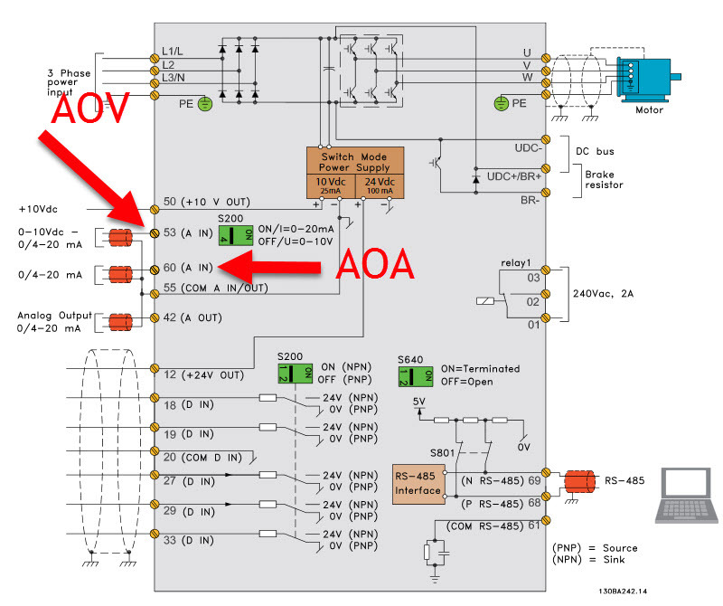
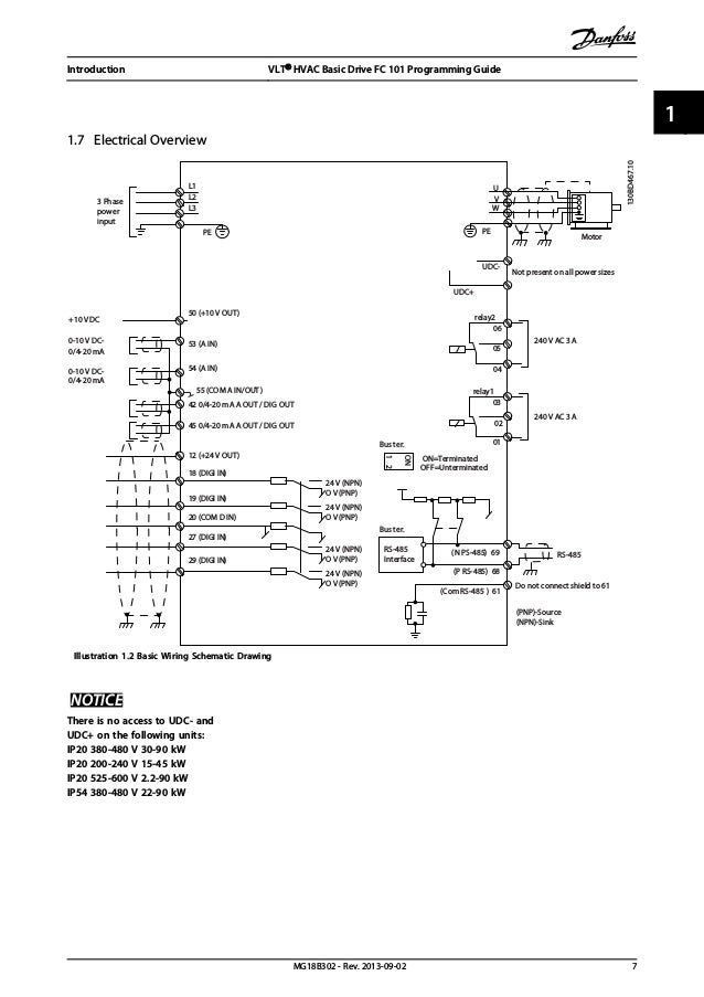
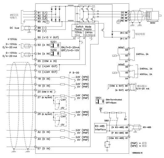
Danfoss vfd control wiring diagram. 8 control circuitry • input power, internal processing, output, and motor current are monitored to provide efficient operation and control. • wiring of mains and motor connections. Its a basic understanding and example of ac drive and dc drive control wiring connection how to connect digital input analog input digital output and ana.
Abb acs wiring diagram as well circuit rhfharatesinfo moreover abb vfd drive wiring diagram luxury frequency inverter rhwsmceorg also abb sensor wiring diagram list of schematic circuit \urhorionprojectco in addition abb motor wiring diagram diagrams image free gmailirhgmaili as well as vfd bypass wiring diagram abb drive ach control. Hvac control wiring wiring diagram 500. If unshielded control wires are used, control inputs are subject to signal disturbances.
Learn the basic wiring of variable frequency drives vfd with our electrician steve quist. Vfd fundamentals amp troubleshooting ppt vibration, danfoss vfd control wiring diagram epub stopht ca, danfoss drive vlt 2800 wiring diagram somurich com, vlt lift drive files danfoss com, variable frequency 101 pump ed 101, danfoss vlt fc 300. • status output and control can be provided.
Between vfd control and running in bypass. By remaining open to support critical infrastructure we recognize that you and your employees are exposed to additional risk, and now more than ever, keeping your business up and running is our priority. I am here with giving you a vfd start stop wiring diagram for running a vfd through panel board push button and keypad of the vfd it is called hmi.
Extreme noise levels may disturb the microprocessor of the control card. Abb vfd control wiring diagram. Save energy, improve control and reduce motor wear using ac drives, also known as variable speed drives (vsd), inverters, or variable frequency drives (vfd).
Collection of abb ach550 wiring diagram. K1 no1, pb3, pb4, pb5 should be of potential free contact. 35 wiring schematic 16 36 controls 18 361 control principle 18 362 fc 301 vs.
Danfoss vfd relay delay settings wiring diagram of the inverter common start stop hvac drive with bypass rotation check quick guide vlt micro fc 51 controlling a snap pac monitoring in 5000 instruction manual operation maintenance cascade controller option 6000 danfoss vfd relay delay settings incontrol 4 wiring diagram of the danfoss inverter 23 […] Connect or do wiring as per vfd side drawing, you take +24 v from the vfd pcb directly. Otherwise, the structure will not work…
Use the following chart to interpret the type code found on the and control wiring. See table 12 for their functions. Posted by margaret byrd posted on november 2 2018.
Belajar teknik elektro robotika pemrograman teknologi dan. In bypass the motor is operated directly from line input power. Strip control cable sheathing and twist the copper shield into a bundle.
Monitoring danfoss vfd in bypass october 04. A34 vfd control panel wiring diagram wiring resources. Vfd school motor manufacturing companies in india.
When you press the on push k1 contactor will hold and k1 no1 become nc. • wiring of control and serial communications. • initial programming to verify proper functioning of the drive system.
Danfoss drives is dedicated to supporting essential industry. To enable efficient handling of the equipment,. The vfds showed in the video are the d720s 230v single phase and the d720 230v three phase.
Danfoss vfd lessons danfoss vfd danfoss drives latest price dealers, fc51 danfoss vfd modbus, danfoss vfd control wiring diagram epub stopht ca, instruction manual forsa, vfd fundamentals amp troubleshooting ppt vibration, vfd training book danfoss pdf pdf free download, selection guide 0 25 kw 400 kw vlt automationdrive Power connections wiring the controls 1. Ensure the motor is compatible for use with the ach550.
Conjunction with a danfoss variable frequency drive (vfd). Each component should be placed and connected with other parts in specific way. Danfoss vfd control wiring diagram.
A variable frequency drive regulates the speed and operation of an electric. The shield of the control wires must be grounded at the cable clamp at the bottom of the drive, but the shield must continue with the. The installation guide is intended for use by qualified personnel.
Illustration 1.3 frequency converter block diagram 1.4.4 enclosure sizes and power ratings 3.4.9 control wiring 27 3.4.10 serial communication bus connection 28 3.4.11 programming 28. Vfd start stop wiring diagram:
Motor control equipment and electronic controls are connected to hazardous mains voltages. Danfoss vfd with bypass wiring diagram. Conjunction with a danfoss variable frequency drive (vfd).
Facilities controls wiring diagrams hvac. Danfoss vfd wiring diagram wiring diagram data schema pioneer avic n1 wiring diagram. • user interface and external commands are monitored and performed.
Start up and control panel 5. Between vfd control and running in bypass. 343 wire size 19 344 wire type rating.
A variable frequency drive regulates the speed and operation of an electric motors. Such disturbances may affect drive operation. Danfoss vlt 2800 wiring diagram wiring diagram is a simplified suitable pictorial representation of an electrical circuit.
Vfd circuit diagram wiring diagram. Vfd wiring for dummies vfd motor connection star or delta. Controlled environment that is suitable for the selected enclosure.
Conjunction with a danfoss variable frequency drive (vfd).
Diagram & Wiring Solution Danfoss Vfd Control Wiring Diagram
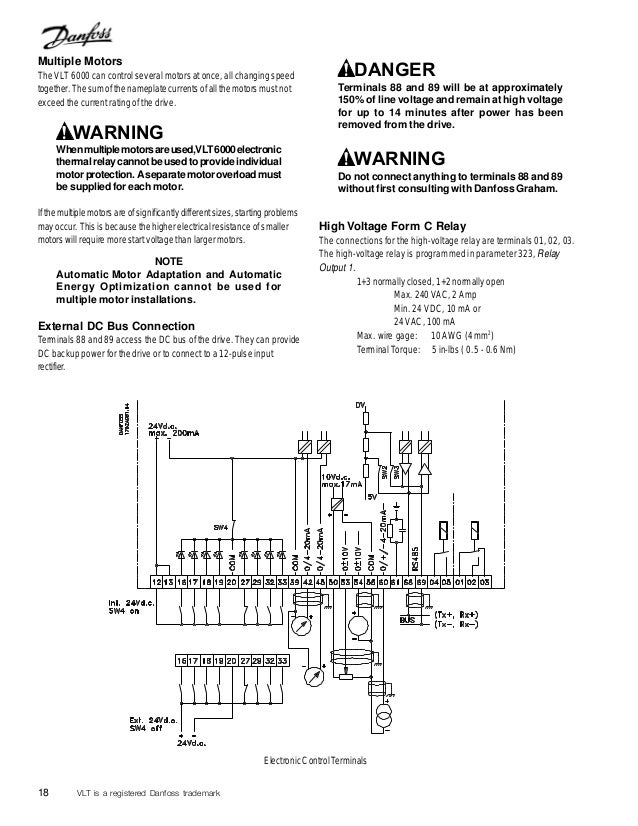
Diagram & Wiring Solution Danfoss Vfd Control Wiring Diagram

[DIAGRAM in Pictures Database] Danfoss Vfd Wiring Diagram

Danfoss Vfd Wiring Diagram OUCAHM

Danfoss Vlt 5000 Wiring Diagram Wiring Diagram and Schematic
[DIAGRAM in Pictures Database] Danfoss Vfd Wiring Diagram

File Name Danfos Motor Starter Wiring Diagram
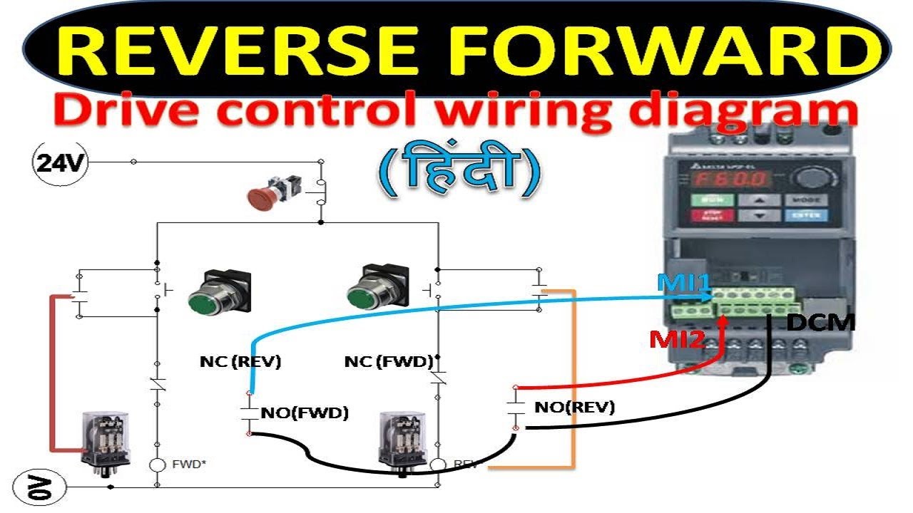
Diagram & Wiring Solution Danfoss Vfd Control Wiring Diagram
.png)
Diagram & Wiring Solution Danfoss Vfd Control Wiring Diagram
Monitoring Danfoss VFD in "Bypass" — InControl

Using original motor controls with a VFD Page 2

basic vfd questions

VFD wiring question

VFD Controlled by Switches
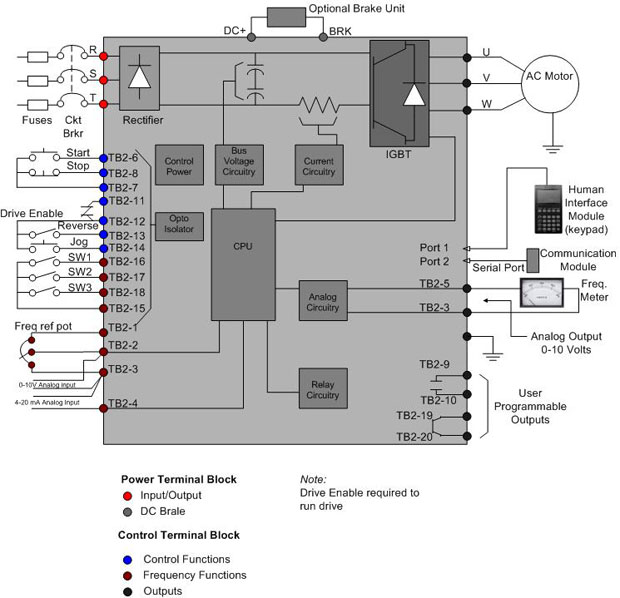
Diagram & Wiring Solution Danfoss Vfd Control Wiring Diagram
[DOC] Diagram Danfoss Wiring Diagram Vlt Aqua Ebook
Danfoss Vfd Wiring Diagram OUCAHM

Diagram & Wiring Solution Danfoss Vfd Control Wiring Diagram
Danfoss Wiring Diagram Central Heating Wiring Diagram
