12v Battery Charger Bridge Rectifier Wiring Diagram
For this purpose we have used two lm317 ics, one is used to control the voltage and the other is used to limit the current.here, in our circuit the ic u1 is used to control the current and the ic u3 is used to. The battery charger pictured here is a real beast.
How to make Simple battery charger circuit

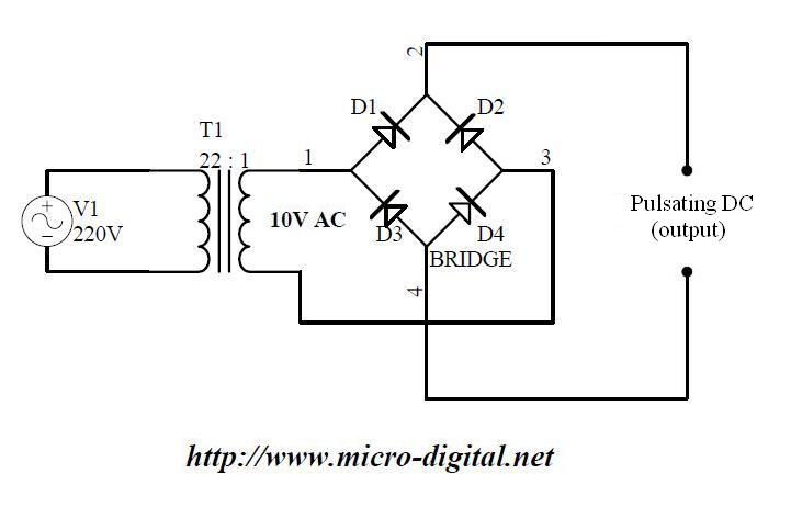
This voltage is now sent to the battery for charging.

12v battery charger bridge rectifier wiring diagram. Use existing products to use more benefits. You can use this circuit to charge 12v sla battery or 12v gel cell battery and so on. The charger is in three stages.
It gives 12 volt and 5 amps current for quick charging of the battery. You can use a readymade 12v 10 a bridge rectifier which is available in the market. Yes, you need a rectifier to do charging;
The component that most often fails is the bridge rectifier. I can’t tell exactly from the info you’ve given. The circuit is a 6v lm317 voltage and current control battery charger circuit which generates a regulated 6v dc output.
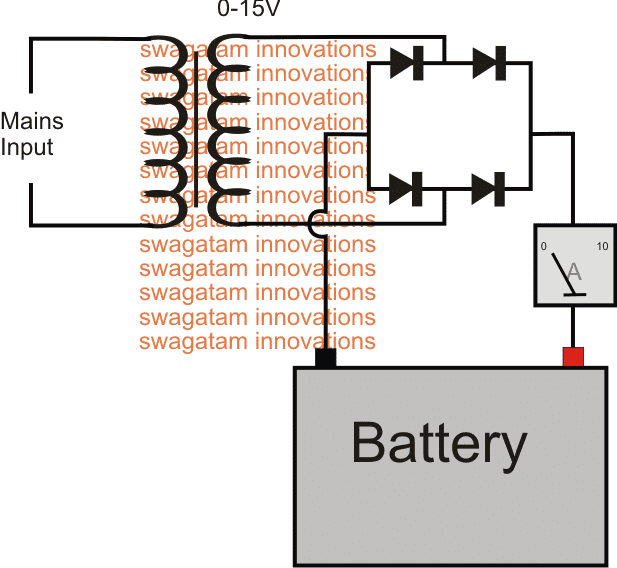
This circuit is designed to provide charging current upto 3 amps and this circuit don’t have reverse polarity. The circuit is nothing but a 12v dc power supply with an ammeter for monitoring the charging current. These are our most commonly requested wiring diagrams suitable for typical customer needs.
Emitter base junction of t1 drops around 12 volts. A lightning strike fried the electronics in this unit, but the transformer. If you want to more high current then replace the transformer with 10a and use 10a10 diode.
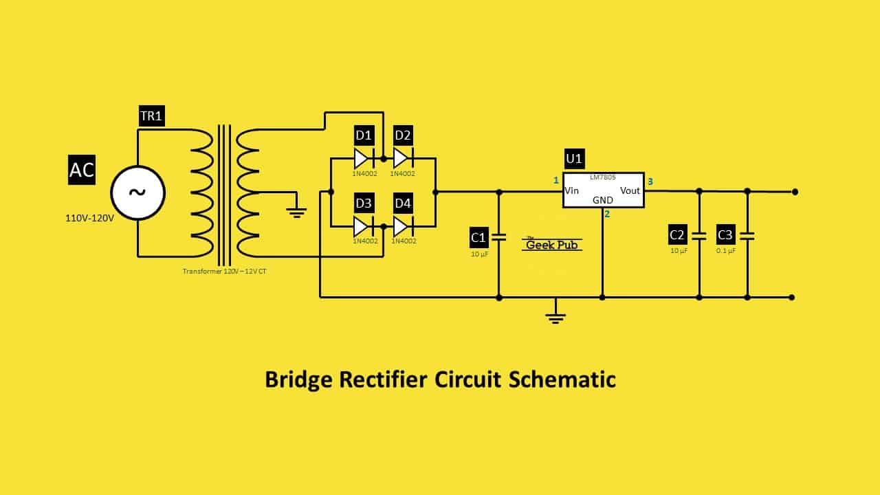
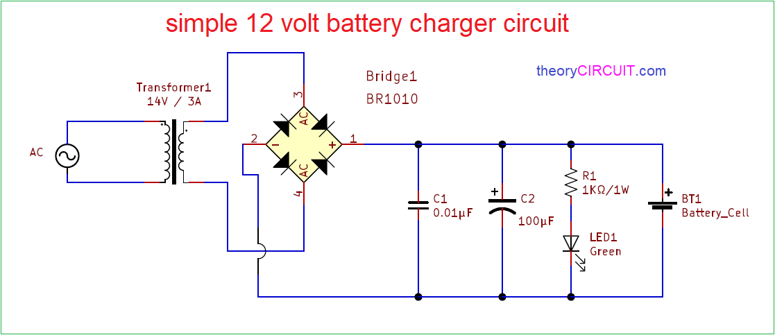
A green led is used for visual indication of a fully charged battery. The capacitor filters the rectifier output to produce a clean 12v output. We use the concept of the circuit:
We can use this circuit for all battery. Check the datasheet and make sure the charger can take 12v input and is good for charging 12v on the output. It will dump 60 amps into a 12 volt battery bank that is low, and will taper down to about 10 amps charging current as the batteries fill.
There’s heaps of chargers made for 12v systems, it’s the most common arrangement. I need to replace the 4 button diodes that is rated at 75amps 400 volts with a bridge rectifier. Not using ics and complicated devices.
This is what i have done for my 12 volt 30amp battery charger psu. The manual says this oulet will produce 80 watts at 12 volts. Just have to understand battery charging requirements only.
A transformer, bridge rectifier, and a capacitor are used to step down the voltage to required 12v then convert and smooth the ac signal to dc. Resistors r1 and pot r2 forms a voltage divider network and the pot r2 can be used for calibration. Battery charger transformer wiring diagram.
In that case, the dome light will remain on all night and the battery will be very low in th… This is the first automatic battery charger circuit. For example, if input voltage is 24v, then output dc voltage is 12v and number of diode used in this type of rectifier is 2.
Very cheap and super reliable high power rectifier. The main objective of our 12v power supply circuit is to control the voltage and current for the battery so that it can be charged in the best possible way. In half bridge rectifier , output voltage is half of the input voltage.
Simple 12 volt battery charger circuit diagram designed by using few easily available components, and this circuit is suitable for different types of batteries needs 12 volt. Do not connect to frame ground. Also i need to instal a rectifier to charge my battery.
Can someone tell me which bridge rectifier i can use to replace these diodes with and how to connect it in the circuit of the charger? The battery charger is originally designed by me to meet the need of some who want a 24v battery charger. Connect to positive(+) battery terminal, and to positive(+) wires of all accessories on the lighting circuit.
Now built your bridge rectifier using these to247. It is handy to have a small battery charger for your automobile, especially if someone parks it in your garage for the night with a door just slightly ajar. Find this pin and more on motors by buckmeir.
Each part should be placed and linked to different parts in particular way. To convert ac into dc, we can make two types of rectifiers, one is half bridge rectifier and second is full bridge rectifier. The circuit uses a 0 14 volt 5 ampere step down transformer and a 10 amps bridge rectifier module to convert ac to dc.
It is designed for 12v batteries. Auto battery charger for 6 or 12 volt sytems: Here is a simple and easy to build circuit diagram of a 12v car battery charger:
The two diodes forms a centre tapped full wave rectifier. After a futile search found these rectifiers are no longer available, so finally got a kbpc2510 metal bridge rectifier. The ac supply is converted to 15v dc with the help of transformer and bridge rectifier and the green led is turned on.
Simple automatic battery charger circuit. The alternator's raw output was. 12 volt battery level indicator circuit diagram.
The button diode is press into a plate two in each row. The dc output is a pulsating dc as there is no filter after the rectifier. Is anyone know the wiring diagram for this rectifier?
Or maybe some chargers have a wide input range (10 to 24v or something). The basis of this charger is dead 1000 watt inverter from heart. If the battery is partially discharged, full charge will be attained in one hour.
This is the circuit of a simple 12 volt battery charger for lead acid battery. Otherwise, the arrangement will not work as it ought to be. Make a simplest battery low voltage indicator for 12v battery.
Free delivery on eligible orders. Transistors are used to detect the voltage of the battery. Automatic 12v battery charger circuit diagram.
For example look at the chassis battery is stated as 12v 20ah.
Automatic Battery Charger Circuit for 12v Leadacid

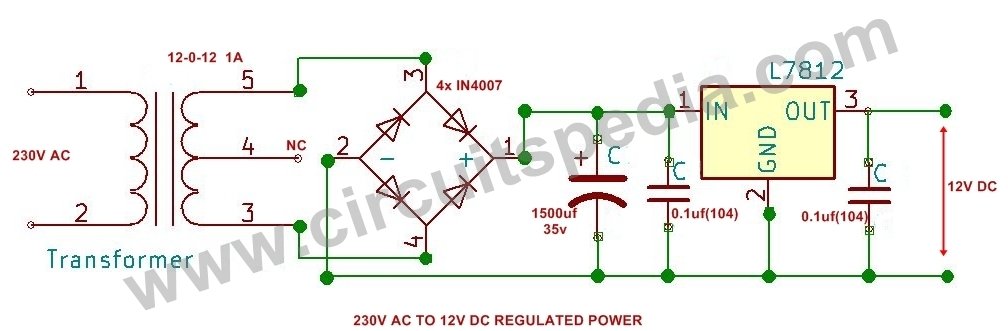
220/230v ac to 12v/5v DC Regulated Power DC converter Bridge Rectifier Simple circuit, Power

Capacitor Bridge Rectifier Circuit
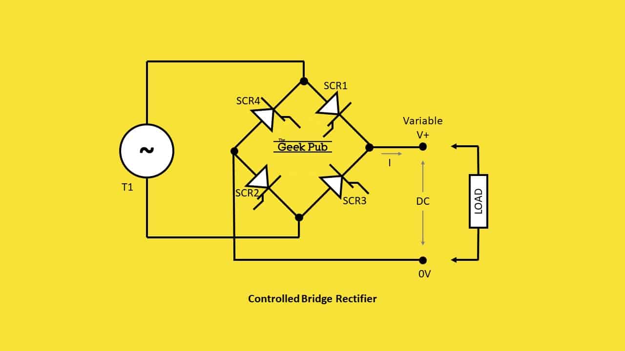
Bridge Rectifier Circuit Electronics Basics The Geek Pub
12v Diode Bridge

220v AC to 12 DC Regulated Converter circuit diagram using Bridge Rectifier
Rectifier Circuit Diagram Half Wave, Full Wave, Bridge ETechnoG

Battery Charger Transformer Wiring Diagram

Bridge Rectifier Wiring Diagram For Your Needs

2 Simple Battery Desulfator Circuits Explored Homemade Circuit Projects
Zener Bridge Rectifier Circuit Diagram

Simple 12 volt Battery Charger Circuit Diagram
Conventional battery charger with bridge rectifier and buck chopper Download Scientific Diagram

Bridge Rectifiers Model Engineer

220/230v ac to 12v/5v DC Regulated Power DC converter Bridge Rectifier Regulators, Power

Battery Charger Circuit for 12V & 6V Batteries

12V SLA Battery Charger Circuit

Bridge Rectifier Circuit Electronics Basics The Geek Pub
Full Wave Bridge Rectifier Supply Micro Digital